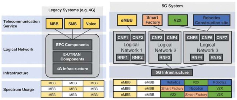
5G sites are currently being installed in a Non-Standalone mode (NSA) together with 4G technology, reusing the legacy infrastructure from current LTE networks. Future 5G deployments will be in a Standalone (SA) mode. This means a new backhaul infrastructure will be dedicated to 5G network services only and built upon fiber or microwave radio.
5G NR is separated into two distinct frequency ranges. Frequency Range 1 (FR1) covers frequencies below 6GHz (also known as sub-6GHz), while Frequency Range (FR2) includes millimeter-wave bands between 24 to 52GHz.
Sub-6GHz frequencies in the FR1 range typically cover channel bandwidths of up to 100MHz, while millimeter-wave frequency bands have shorter range but offer higher available channel bandwidths up to 400MHz. In 5G NR, Subcarrier Spacing (SCS) varies from 15kHz up to 240kHz. Default values for SCS are 15 or 30kHz for FR1 and 120 or 240 kHz for FR2. The signal multiplexing for FR2 is dynamic TDD, while for FR1, FDD or TDD may be used. Together with 5G massive MIMO technique, 4 beams are about to be used for frequencies below 3GHz, 8 beams for frequencies from 3 up to 6GHz, while 64 beams may be used from 6 up to 52GHz.
5G NR SSB
5GNR SSB stands for Synchronization and Signal Block and is the 5G NR equivalent of LTE Reference Signal. For user equipment (UE) to communicate with a 5G NR network, it needs to acquire necessary system information by performing cell-search to find, identify, and synchronize with a specific cell. Cell search is also essential for mobility, handover, and cell reselection purposes.
The 5G NR SSB consists of a Primary Synchronization Signal (PSS), Secondary Synchronization Signal (SS), and Primary Broadcast Channel (PBCH) channels. Multiple SSBs are transmitted periodically at 20ms intervals. The SS block period may vary from 5ms to 160ms, however, during an initial cell search, the SSB is repeated at least once every 20ms. In FR2, up to 64 SSBs may be transmitted in different beams within an SS burst set period.
In 5G NR, an SSB can be transmitted in different beams in the time domain. This set of SSBs within a beam-sweep is known as an SS burst. A UE may only read the single SSB of a specific downlink beam, without taking into account any other SSBs transmitted from the same cell. In the time domain, four OFDM symbols are used. For SSB, the PSS is transmitted in the first OFDM symbol, the SSS in the third, and PBCH in the second and fourth.
In the frequency domain, for LTE, the PSS and SSS were located at the center of the carrier. However, this is not the case with NR. The 5G NR synchronization raster indicates the frequency positions of the synchronization block (SSB) that can be used by the UE for system acquisition when the SSB position is not known.
The frequency position of the SSB is defined as SSREF, with the corresponding number defined as Global Synchronization Channel Number (GSCN).
5G NR Testing
Challenges
The key difference of 5G radio technology is that we are now dealing with TDD technology with burst signals and multi-reference signals (Beams). This means that we need new testing domains such as Power vs Time and Time vs Frequency. New RAN architecture requires fronthaul and over-the-air (OTA) measurements. Effective interference analysis for TDD requires real-time spectrum analyzers and persistent spectrum views. RF measurements require automated triggered spectrum analysis for 5G burst type of signal. TDD measurements require automated downlink discrimination from the uplink. Dedicated beam and carrier analysis are needed, while route map function is required for coverage and propagation analysis for either an outdoor or indoor environment.
5G NR testing procedure
The typical testing procedure is to confirm the center frequency (channel number) and signal bandwidth of the transmitting carriers. Then, confirm the SSB frequency location and Subcarrier Spacing (SCS). Verification is needed that all carriers are transmitting at correct power levels and confirm PCI value per carrier. The Physical Cell ID (PCI) is the site identifier of each cell-site. Furthermore, verification of the (SSB) Beam Indexes for each carrier, including the quality of the PBCH transmission. Carrier scanning can be used to identify the physical cell Id, beam Id, carrier frequency and power, beam power, and quality. 5G NR site coverage (including RSRP and SINR values) needs also to be verified, together with signal propagation.
5G NR Beam Index analysis
5G gNB may broadcast up to 64 Beam IDs, originating at specific angles from the antenna panel, resulting in Beam Indexes covering different geographical locations around the cell site sector (beamforming). Beam analysis can be stationary or in a drive/walk mode depending on the specific use case (e.g., FWA or mobility) and whether the coverage area under testing is either indoor or outdoor. Beam Information such as cell ID, Beam ID (Ant, Sym), RSRP, RSRQ, SINR can be recorded.
5GNR coverage validation
Coverage mapping analysis (drive, walk) requires the use of FR1 or FR2 Omni antennas and not directional. Each measured point should contain the time, lat-long, PCI, Beam Index, RSRP, RSRQ, SINR on SS, or PS signals.

