Dual Connectivity (DC)
E-UTRAN supports Dual Connectivity (DC) operation whereby a multiple Rx/Tx UE in RRC_CONNECTED is configured to utilize radio resources provided by two distinct schedulers, located in two nodes connected via a non-ideal backhaul over the X2 interface.
is involved in DC for a certain UE may assume two different roles: an eNB may either act as a MeNB or as a SeNB. In DC a UE is connected to one MeNB and one SeNB.
- MeNB: Master eNB
- SeNB: Secondary eNB
In DC, the radio protocol architecture that a particular bearer uses depends on how the bearer is setup. Three bearer types exist MCG bearer, SCG bearer, and split bearer. Those three bearer types are depicted below. RRC is located in MeNB and SRBs (Signalling Radio Bearer) are always configured as MCG bearer type and therefore only use the radio resources of the MeNB.
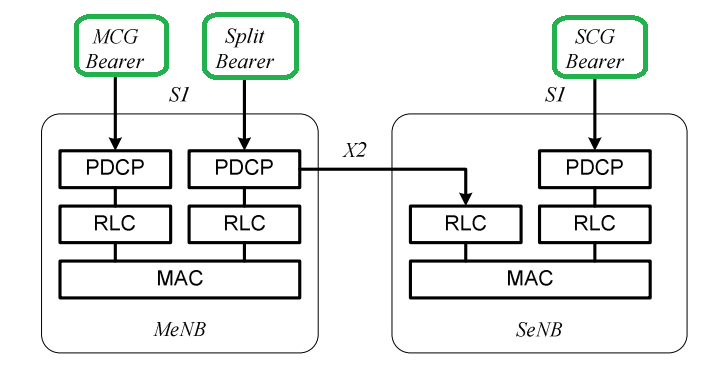
Radio Protocol Architecture for Dual Connectivity
- MCG bearer: in dual connectivity, a bearer whose radio protocols are only located in the MeNB to use MeNB resources only.
- SCG bearer: in dual connectivity, a bearer whose radio protocols are only located in the SeNB to use SeNB resources.
- Split bearer: in dual connectivity, a bearer whose radio protocols are located in both the MeNB and the SeNB to use both MeNB and SeNB resources.
MR-DC with the EPC
E-UTRAN supports MR-DC via E-UTRA-NR Dual Connectivity (EN-DC), in which a UE is connected to one eNB that acts as an MN and one en-gNB that acts as an SN. The eNB is connected to the EPC via the S1 interface and to the en-gNB via the X2 interface. The en-gNB might also be connected to the EPC via the S1-U interface and other en-gNBs via the X2-U interface.
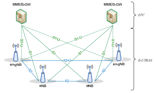
EN-DC Overall Architecture
MR-DC with the 5GC
There are three possible MR-DC with the 5GC architectures as follow
- E-UTRA-NR Dual Connectivity
NG-RAN supports NG-RAN E-UTRA-NR Dual Connectivity (NGEN-DC), in which a UE is connected to one ng-eNB that acts as an MN and one gNB that acts as an SN. The ng-eNB is connected to the 5GC and the gNB is connected to the ng-eNB via the Xn interface. - NR-E-UTRA Dual Connectivity
NG-RAN supports NR-E-UTRA Dual Connectivity (NE-DC), in which a UE is connected to one gNB that acts as an MN and one ng-eNB that acts as an SN. The gNB is connected to 5GC and the ng-eNB is connected to the gNB via the Xn interface. - NR-NR Dual Connectivity
NG-RAN supports NR-NR Dual Connectivity (NR-DC), in which a UE is connected to one gNB that acts as an MN and another gNB that acts as an SN. The master gNB is connected to the 5GC via the NG interface and to the secondary gNB via the Xn interface. The secondary gNB might also be connected to the 5GC via the NG-U interface. In addition, NRDC can also be used when a UE is connected to two gNB-DUs, one serving the MCG and the other serving the SCG, connected to the same gNB-CU, acting both as an MN and as an SN.
EN-DC Scenarios
The EN-DC architecture is suitable for deployment scenarios that only introduce 5G NR and do not introduce 5GC. In this architecture, the anchors of the control plane are always located in the LTE RAN, that is, the S1-C interface is terminated by eNB. It can be further divided into three types of networking architecture in the sight of different user plane aggregation point and distribution flow types, as shown below:
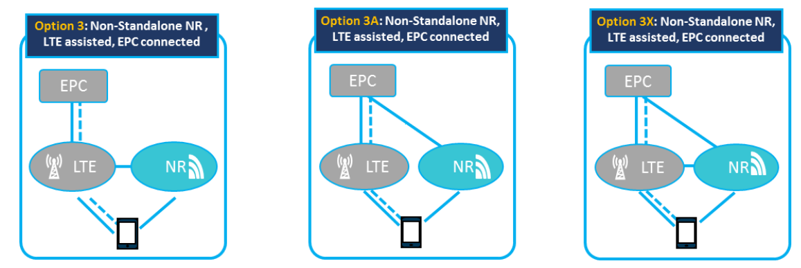
EN-DC Scenarios
- Option 3 networking: eNB also terminates S1-U interface, and NR gNB hasn’t any interface to EPC. The traffic flow is converged at the eNB PDCP layer and divided from the eNB to the gNB via the X2 interface. In this architecture, eNB nodes will carry a large amount of traffic and corresponding computing work. So the eNB hardware has to be upgraded to avoid becoming a bottleneck. Correspondingly, the backhaul to the core network and between the two nodes also need to be improved.
- Option 3A networking: gNB also has S1-U interface to EPC. Traffic flows are split in the core network, and the different service bearers can be carried in LTE or 5G NR. In this architecture, eNB can migrate the services that need high throughput or ultra-low latency to the NR Node, reducing the requirement of processing capacity for itself. And because there is no split mechanism, the demand for the X2 backhaul is
easy to meet. - Option 3X networking: gNB has S1-U interface to EPC. The traffic flow is converged at the gNB PDCP layer and divided from the gNB to the eNB via the X2 interface. In this architecture, the new 5G NR with high performance carries on most of the traffic and avoids the excessive upgrade and transformation to the existing RAN and transport network. When the NR coverage is poor, the LTE side also can provide robustness using a traffic flow split mechanism with a smaller bandwidth requirement of X2 backhaul.
NGEN-DC Scenarios
A UE is connected one evolved eNB that acts as a MN and one gNB that act as an SN. The evolved eNB is connected to the new 5GC via NG-C and NG-U interface, and the gNB is connected to 5GC via the NG-U interface. The evolved eNB and the gNB connect each other via the Xn interface. The MR-DC mechanism is called NG-RAN E-UTRA-NR dual connectivity (NGEN-DC).
The NGEN-DC architecture is suitable for deployment scenarios that LTE RAN has been upgraded to support 5GC. In this architecture, the anchors of the control plane are always located in the eLTE RAN. Like EN-DC, it can also be divided into three architectures as shown below:
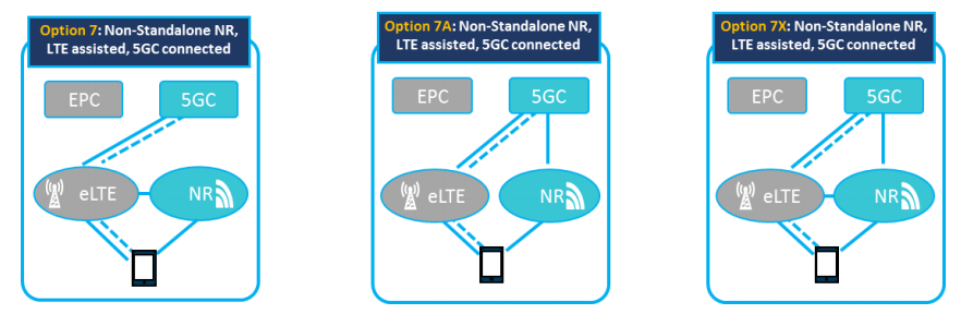
NGEN-DC Scenarios
NE-DC Scenarios
A UE is connected one gNB that acts as a MN and one evolved eNB that acts as a SN. The gNB is connected to the new 5GC via NG-C and NG-U interface, and the evolved eNB is connected to 5GC via the NG-U interface. The gNB and the evolved eNB connect each other via the Xn interface. The MR-DC mechanism is called NR-E-UTRA dual connectivity (NE-DC).
The NGEN-DC architecture is suitable for deployment scenarios that 5G NR can provide continuous coverage. In this architecture, the anchors of the control plane are always located in the 5G NR. Because 5G NR has a stronger capability and greater capacity, so the architecture that traffic is divided from SN (eLTE) to MN (NR) is no longer needed. So Option 4 contains only include two architectures: Option 4 and 4A.
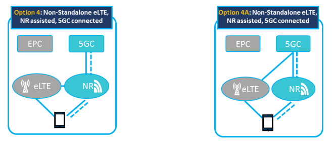
NE-DC Scenarios
References:
- 3GPP TS 37.340 version 15.5.0 Release 15.
- 3GPP TS 28.540 version 15.1.0 Release 15.
- GTI 5G Network Architecture White Paper.


