In order to meet the new requirements of 5G networks, 3GPP initialed the development and standardization of a new radio-access technology known as 5G New Radio (NR). 5G Non-Standalone (NSA) architecture was initially introduced by 3GPP, and its specification was completed in late 2017 to accelerate time to market. 5G NSA is the most suitable solution for 5G early deployment and for complementing NR coverage as full mobility with LTE is supported. 5G NSA avoids high effort and supports easy implementation since the 5G Core is integrated into legacy core, the evolved Packet Core (ePC).
5G Standalone specification was completed in June 2018 with Release 15. 5G Stand-Alone (SA) architecture is a long term strategy for any Mobile Carrier since the NSA architecture will probably be maintained for some time in the networks. This is because a full hardware swap will be needed to support 5G SA, and the first 5G devices will support only NSA for quite some time.
Standalone Architecture with 5G Core Network (CN) supports the separation of User Plane (UP) functions from Control Plane (CP) to allow independent scalability, evolution path, and flexible deployment. A 5G SA architecture enables deployment with Network Function Virtualization and Software Defined Networking. The function design is based on modules and allows flexible and efficient network slicing.
5G SA CU/DU split
5G NR SA architecture and interfaces are similar to LTE. According to 3GPP TR38.801, the typical baseband (BBU) unit of LTE, in 5G NR is now split into the Central Unit (CU), and the Distributed Unit (DU). This CU/DU split will help to adopt a flexible architecture with various deployment scenarios, meet 5G latency demands, and reduce the overall fronthaul capacity needs. CU/DU split will be standardized in LTE as well, to enable closer interoperability and common platform deployment. A mixed architecture is where LTE is connected over the S1 interface towards the ePC, and 5G NR is connected over Nx interfaces to the 5G Core. This type of architecture is suitable for incumbent players, however, difficult to be maintained and supported by new entrants.
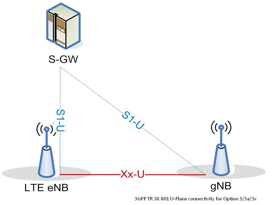
3GPP deployment Option 3x
There are many deployment scenarios specified by 3GPP for 5G non-standalone and standalone operation, depending on shared or different interfaces to the ePC/5GC, the user plane split, and the control plane anchor. One example which is strongly preferred by major incumbent carriers is deployment scenario Option 3x. In 3GPP Option 3x, the control and user plane are shared between the eNB and gNB, while 10GE and NR-bearer ciphering is done at the gNB. This minimizes the hardware impact on the eNB. Option 3x has to be also used in the future, as long as terminals supporting it will be in use.
Option 3x has a minimum impact on legacy LTE for user plane data split. A dynamic user plane data split in RAN at the packet level provides better performance. Option 3x solution is based on dual connectivity, with a common Core network. This will allow mobility robustness considering inadequate NR coverage in the 3.5 GHz band that will help overcome propagation challenges with Supplemental Uplink.
EUTRA-NR Dual Connectivity
The limited coverage of 3.5 GHz NR requires the user equipment device to anchor in a lower band coverage layer for mobility robustness. The user equipment is connected to one eNB that acts as a Master Node (MN/MeNB) and one gNB that acts as a Secondary Node (SN/SGNB). The higher band is only used for throughput boost (primarily DL, but UL also possible). The anchor point is at the Packet Data Convergence Protocol (PDCP) layer, as that is the point where the data is split between LTE and NR.
The control plane signaling is done via the eNB. The eNB is connected to the EPC via the S1 interface and to the gNB via X2-C and X2-U interface and provides the Master Cell Group (MGC). The gNB is connected to the EPC via the S1-U interface and provides the Secondary Cell Group (SGC).
Both Co-site and non-co-site deployment options are possible. Vendors require time synchronization between the eNB and gNB. Although 3GPP claims it is not needed, some functions might actually require time synch such as TDM uplink power control (reaching 23dBm on both RATs, through TDM) and TDM interference avoidance (2nd inter-modulation avoidance and 2nd harmonic avoidance).
DL Split bearer & Dual Connectivity
Downlink data can be sent either in a single bearer (Master Node or Secondary Node), based on buffer size. Under low buffering conditions, 5G NR is used, while under full buffer conditions, LTE + NR is used. In this case, the Uplink and Downlink switch operates independently. Dual Connectivity aggregation transmission mode sends downlink data in both LTE and 5G NR for higher throughput. Flow control in both nodes will guarantee packet order in the User Equipment device.
UL Split bearer & Dual Connectivity
Uplink data can be sent in single bearer (either Master Node or Secondary Node), based on configuration, uplink radio channel quality, and buffer size. Under good radio conditions and full uplink buffering, both 5G NR and LTE can be used. Under moderate radio conditions, NR or low buffer is used. Under poor radio conditions, only LTE is used. Some vendors support uplink packet aggregation, others don’t. There is an option to place all Uplink data on LTE only, regardless of radio conditions or buffer size.
SgNB mobility management
At the early stages of 5G deployment in NSA mode, in most cases, the NR will be used as a secondary node (SN) to the LTE master node (MN). The bearer is set up as MN with user plane data over LTE radio only. In order to set up the NR Leg, the bearer is reconfigured to an SN-terminated Split data radio bearer (DRB) with a change of PDCP version and security key. The setup can be either measurement-based (B1) or configuration-based (blind). For the NR Leg Release, the bearer type is changed to MN-terminated MCG DRB. Also, the PDCP version and security key are changed. The NR Leg release is triggered by NR RLF, NR Cell lock, etc. The user equipment is released to idle mode, where any resources for the Split DRB in the eNB and the gNB are released to idle Mode.


