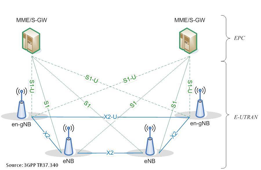
5G E-UTRAN New Radio Dual Connectivity (EN-DC) architecture is the leading 5G architecture for the support of the initial 5G Enhanced Mobile Broadband (eMBB) services. In principle, there are no significant differences regarding protocols and interfaces to the standard LTE architecture, since S1 and X2 interfaces are used. According to 3GPP, the air interface for LTE, as well as for 5G New Radio, is called the Uu interface. The NR air interface is either referred to as NR-Uu or just NR. The LTE air interface is correspondingly named LTE-Uu. In EN-DC architecture, a User Equipment (UE) establishes connections to an eNodeB that acts as a master node and to a gNodeB that acts as a secondary node. The eNodeB is connected to the ePC via the S1 interface and to the en-gNodeB via the X2 interface.
S1 Interface
The S1 interface consists of S1-MME for the control plane, while the S1AP is the application layer signaling protocol. S1-MME, also known as S1-C, is the reference point for the control plane protocol between E-UTRAN and the MME. S1-MME uses the SCTP protocol stack for S1AP control plane transport. The SCTP signaling associations are automatically set up at eNodeB start-up. For each MME, the eNodeB initializes an SCTP association as described in IETF RFC4960 using an OAM configured initial remote IP endpoint as the starting point until SCTP connectivity is established. The eNodeB can be connected to several MMEs over the S1 flex protocol. In S1 flex configuration, a NAS node selection algorithm selects an appropriate MME based on various possible inputs.
S1-U is the reference point between E-UTRAN and Serving GW for the per bearer user plane tunneling and inter eNodeB path switching during handover. The S1-U is for the user plane, and it uses a logical S1 transport bearer. An S1 transport bearer is composed of two opposite directed unidirectional GTP-U tunnels between the eNodeB and the S-GW. The Uplink tunnel is identified by the Downlink GTP-TEID (Tunnel endpoint identifier) and IP address in the S-GW, while the Downlink tunnel is identified by DL GTP-TEID and IP address in the eNodeB. On S1, the eNodeB uses the same local IP address for uplink and downlink. The selected local IP interface is used during the established bearer connection. The uplink user data tunnel is created by the S-GW, which informs, via S1AP signaling over S1 and S1-MME, the eNodeB about the Uplink TEID and Transport IP Address. In a similar manner, the downlink user data tunnel is created by the eNodeB, which informs, via S1AP signaling, the S-GW about the Downlink TEID and Transport IP Address. Some Operators use full S1 flex functionality for the S1-U interface. Up to 32 SGWs can be used within an SGW pool. Each eNodeB is connected to one SGW pool.
X2 Interface
In 5G NR, any connectivity between 2 eNodeBs as well as between en-gNodeB and eNodeB is still called the X2 interface. According to TS38.420, the Xn interface describes the interface between 2 gNodeBs in an SA architecture, so it is not applicable in EN-DC. Some Operators enable the X2 interface to support intra-LTE active mode mobility. For security reasons, the X2 interface might need to be ciphered, which means IPSec tunnels will be used. In general, two possible IPSec configurations for the X2 interface are possible. The first one is a direct X2 connection from eNodeB directly to neighbor eNodeB. In this configuration, the eNodeB needs to support IPSec tunnels for each neighboring eNodeB. In indirect X2 connections over IPSec gateway, the X2 interface traffic will be included in the existing IPSec tunnels between the eNodeB and the IPSec gateway. The longer transfer delay on the X2 interface in this configuration has no significant impact. For the onsite communication between eNodeB and en-gNodeB via the X2 interface, a direct x2 connection is assumed. In case the same supplier for eNodeB and en-gNodeB is used, internal links are also sometimes offered. However, the routing via the transport network needs to avoid “non-open” X2 interfaces in the future. For the X2 interface between 2 eNodeBs or between 2 en-gNodeBs, the same setup can be used. In general, a direct X2 connection is preferred, but due to the limited number of parallel IP-Sec tunnels, this is not possible with all RAN vendors.
EN-DC Deployment Scenarios
In a dual connectivity (EN-DC) deployment, the UE maintains simultaneously two radio links of the same or different Radio Access Technology. As LTE is typically using an FDD band supporting continuous uplink transmission, a 23 dB total power limit applies. For EN-DC, the UE is connected to an eNodeB operating at a lower frequency band and to a gNodeB operating at a higher frequency band such as the 3.6 GHz. For co-located deployments, the UE may transmit uplink packets at the uplink part of the paired frequency band, typically used by LTE, and the uplink timeslots at the higher frequency band used by NR in TDD. For non-collocated deployments, the UE may transmit simultaneously. The available UE power would be split either in static or dynamic sharing mode between the two links. In static sharing, if a high power UE with a total average power of 23 dBm is used, the power will be split in half (20dBm) for each link in the different frequency bands. To avoid this power split, in a co-sited deployment, the network can ensure that TDM is used, so there is no need for the UE to transmit on NR and LTE simultaneously. This way, in a typical EN-DC scenario, the maximum UE transmission power used at the cell edge is 23 dBm. However, the use of TDM also implies the use of LTE TDD frame configuration for LTE, and this may reduce the overall data rate.
EN–DC with Supplemental Uplink
The uplink coverage is typically limited due to power restrictions in the UE. Therefore, if a UE uses a lower frequency band for uplink transmission, it will achieve coverage extension as the downlink coverage at higher frequency bands will be matched. The difference of EN-DC with the Supplemental Uplink scenario is that the NR initial access procedure and physical layer control signaling channels cannot be carried over the unused LTE uplink resources. This means that there will be no range extension for these control channels by the use of the lower frequency band as in SUL. Thus NR coverage will be limited by these control channels needed to maintain a flow for NR downlink data. In the Supplemental Uplink scenario, it is assumed that the UE will transmit with maximum power 23dBm in a time-duplexing mode either in the lower frequency band (i.e., for LTE or NR UL data/control channels) or in the higher frequency band, i.e., for SRS.


