Introduction
5G is rapidly coming close bringing with it the promise of powerful new use cases that will require a flexible technology that can provide ultra-reliable low latency (uRLLC), massive machine-type communications (mMTC), and much huge faster data rates with enhanced Mobile Broadband (eMBB).
As mobile operators started their 5G deployment plans, they should also determine how best to deliver 5G data throughput most effectively.
So in this article, we will discuss the calculation for the maximum 5G NR throughput to get a rough estimate about the upper bound on the throughput that the 5G system can provide.
The formula for 5G NR throughput calculation
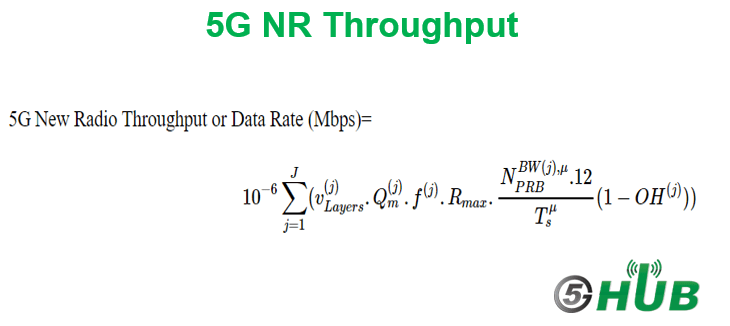
According to 3GPP TS 38.306, the approximate maximum data transfer rate is calculated using the following equation.
5G New Radio Throughput (Mbps) =
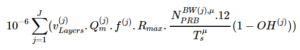
This equation has different parameters and the details of each one are as below:
J: the number of aggregated components carriers (CC) in a band or band combination.
In 5G NR, the maximum number of CC is 16 components carriers as that can be merged to achieve higher BW which helps to improve the 5G System throughput and performance.
J (Maximum Value) =16
V(j): represents the maximum number of MIMO layers.
In MIMO, the number of layers is very similar to the term stream and also the number of the layer can’t be more than the antennas number.
V(j) (Maximum Value) = 8 in DL and 4 in UL.
Q(j)m: represents the maximum modulation order.
The modulation order means the number of different symbols can be transmitted using the digital communication system.
5G NR supports different modulation types QPSK (2), 16QAM (4), 64QAM (6) and 256QAM (8).
f(j): Scaling factor, is used for Medium and High mobility and should be configured per Carriers.
It can take the following values 0.4, 0.75, 0.8, and 1.
Rmax: Value depends on the type of coding and for LDPC code maximum number is 948/1024 = 0.92578125 (from 3GPP MCS Index table).
N BW(j), PRB: Number of allocated PRBs per BW per subcarrier spacing (up to 273 for 30Khz on 100MHz bandwidth).
The maximum transmission bandwidth configuration NRB for each UE channel bandwidth and subcarrier spacing are specified in the tables below:
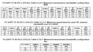
Tμs(j) = average OFDM symbol duration in a subframe for μ(i) value for normal cyclic prefix.
μ(i) = 0,1,2,3,4,5
For normal cyclic prefix, Tμs(j) = (10^-3)/(14*2^μ)
OH(j): represents the overhead for control channels.
It can take the following values:
- Its value is 0.14 for FR1 (FR 1) for downlink
- Its value is 0.18 for FR2 (FR 2) for downlink
- Its value is 0.08 for FR1 (FR 1) for uplink
- Its value is 0.10 for FR2 (FR 2) for uplink
Example:
Let’s assume that a network operator does have 100 MHz of spectrum in the 3.5 GHz range for 5G NR.
In this case, the DL maximum throughput FDD will be calculated as below:
- J=1 as we have here one carrier component
- v(j) = 4 assuming 4 layer in DL.
- Q(j)m = 8 assuming the modulation order is 256QAM
- f(j) = 1 assuming scaling factor=1
- Rmax = 925
- BW:100MHz FR1
- µ:1 for subcarrier spacing 30KHz
- NbwPRB = 273
- Tμs(j) = 10^-3 / (14*2)
- OH(j) = 0.14 for FR1 DL
DL Data Rate (in Mbps) =10^-6 * 1*4*8*0.925*(273*12)*(14*2)*(1-0.14)= 2337 Mbps = 2.34 Gbps
References:
-
- 3GPP TS 38.306


