Antenna technology will play an essential role in the initial implementation of 5G networks. New advanced antenna techniques are developed to ensure the capacities and efficiency needed to support the new 5G system requirements.
Antenna Basics
A basic dipole antenna system consists of an RF signal which is fed into a two wire conductor. Between the two wires, an electrical field is created. By bending the wires by 90°, the electrical field can leave the conductors, and the established λ/2-dipole system is radiating an Electromagnetic Field (EMF).
The λ/2-dipole is a typical Omnidirectional Antenna. This means the antenna has no main lobe direction, so the horizontal radiation pattern is circular. A passive antenna has typically 8 to 12 dipoles for one frequency band, arranged in one column.
Today’s networks are mainly deployed with sector antennas. This means that the pattern is pointing into a specific direction, the main lobe direction. This technique is achieved by placing a reflector beyond a particular area of the column of dipoles. The power is reflected by the reflector so that the power to the main lobe direction increases. Therefore, sector antennas have more gain than Omni Antennas pointing to a specific direction.
Antenna deployment evolution
In initial GSM-900MHz system deployments, Omni Antennas (8dBi) were typically used. There was one antenna in the middle/top position used for Transmission (TX, Downlink) and two Antennas for Receiving (RX, Uplink). These Antennas have one RF Connector.
By replacing the Omni Antennas with Sector Antennas, the site capacity has been multiplied by almost a factor of 3. Coverage has also increased due to the increased gain of the Sector Antennas. For saving space purposes, one of the sector antennas is typically used for RX and TX, and the second antenna for the RX2 path. These antenna panels have one RF connector each.
In order to introduce a new frequency band, Vertical Polarized Antennas have been replaced by Cross Polarized Antennas. One X-Polarized Antenna Panel contains 2 Arrays of Dipoles. For having maximum receiver diversity performance, each of the dipole elements is tilted by 45°.
Trials displayed that X-Pol antennas show excellent RX-diversity performance in urban areas, where the coverage depends heavily on reflections. For rural areas, V-Pol Antennas are still the better choice, but as the X-Pol Antennas require less space for deployment, the compromise for going X-Pol everywhere has been accepted globally. X-Pol antenna panels have two RF connectors, one for +45° one for -45°.
Adding the UMTS in the 3rd frequency band brought the introduction of multi X-Pol Antennas. As the number of frequency bands on the same sites increases and the number of antenna panels per sector is typically limited to two, more than one Array of X-Dipoles has to be packed into a single antenna panel. The XX-Pol Antenna has 4 RF Connectors, compared to the typical X-Pol Antenna with 2 RF Connectors.
Active Antenna Systems
Passive Antenna Systems (PAS) have one RF Port per Antenna Array, each connected to one RF Unit of the Remote Radio Module (RRM). The RRM is connected to the Base Band Unit (BBU) via an optical fiber connection. Active Antenna Systems (AAS) have several RF Units integrated, and connected to the dipoles of the antenna arrays.
By the use of advanced techniques such as MIMO, with two Transmitter Antennas (Tx) and two Receiver Antennas (Rx), the capacity on the Air Interface is doubled.
Downlink Single User MIMO (su-MIMO) is applicable in LTE systems, where one user is allocated time-frequency resources through all layers, and user-specific beam-forming provides array gain. SINR increases as the number of antennas increases and improves coverage, without, however, providing higher capacity.
In Multi-user MIMO (mu-MIMO), adopted by 5G-NR, multiple users are sharing the same time-frequency resources. Due to the high capacity gain, this technique is more beneficial in bandwidth-limited scenarios, or in a high-load situation.
Antenna Systems for 5G deployment
Today’s common practice for a typical site with 2 antenna poles, is that one antenna is deployed for all high-bands and one antenna for all low-bands. For a 5G ready site design, all legacy systems (2G, 3G & 4G) have to use the one antenna panel (passive or active) to leave space for the deployment of the 5G AAS antenna system.
In a 16TRX antenna system, there is no vertical beam-forming, due to missing vertical sub arrays. Since using 16TRX does not bring any vertical beams this solution is limited in capacity.
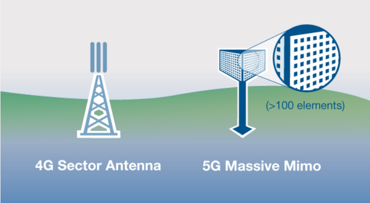
An area with high-size buildings such as skyscrapers is the most suitable environment for 64TRX m-MIMO antenna (Vertical beam-forming with 4 vertical sub-arrays). However, deployment of 64TRX m-MIMO antenna in a suburban environment may lead to unused vertical beams, with inefficient utilization.
A typical potential product positioning would, therefore, be 64TRX in a dense urban environment, 32TRX in suburban and 16 TRX in rural setting accordingly.
Dense Urban (64TRX) is mostly foreseen in SE Asia and N America, while urban-suburban (32TRX) applies to medium-sized buildings, which is the majority of the European cities. Rural (16TRX) can be used in a typical low-size building environment.
5G Antenna Strategy
5G Telecom Operators are investigating their strategy regarding 5G antenna systems and 5G early deployment. Factors such as capacity, price and power consumption need to be considered for the appropriate antenna selection.
There is a considerable risk to overinvest and run into an underutilization of assets discussion. For example, massive MIMO, beam-forming antennas for 5G in 3.5GHz may cause significant costs, and this could bear the risk to create high OPEX costs.
The coverage provided by 3,5GHz is limited, with UL being the limiting factor. This limitation is due to the restriction in UE TX power. 3,5GHz with M-MIMO antenna provides approximately half the cell range as LTE 1800 (1/4 of the area). More antenna systems need to be deployed to cover the same area, so careful planning is a key aspect.
5G Telecom Operators have to decide on their antenna strategy for 5G Early Deployment. As mentioned above, 64TRX m-MIMO Antennas may not seem initially deployable for most of Europe, and even in Asia, the tendency lately is to start with 32TRX. There is also the trend to use 32 TRX as the standard antenna type for initial rollout in urban areas, and even 16TRX needs to be evaluated. Vendors, on the other hand, need to guarantee on-time delivery of at least 32/16TRX antennas. This way the technology will evolve into a solid ground for reasonable 5G network investments.


