
Introduction
The 3GPP Release 18 introduces a range of enhancements aimed at optimizing the performance and efficiency of 5G New Radio. Among these advancements is a strong focus on improving the capabilities of NR Frequency Range 2 (FR2), which encompasses the millimeter-wave (mmWave) spectrum, specifically the frequencies between 24 GHz and 52.6 GHz.
FR2, with its promise of ultra-high data rates and increased network capacity, plays a pivotal role in realizing the full potential of 5G, particularly for demanding applications such as Massive Machine Type Communications (mMTC) and Industrial IoT (IIoT). However, the unique characteristics of the mmWave spectrum—such as higher path loss, susceptibility to blockages, and the need for precise beamforming—pose significant challenges for both network operators and device manufacturers. To address these challenges, 3GPP Release 18 introduces comprehensive enhancements in Over-the-Air (OTA) testing methodologies, particularly tailored for FR2, ensuring that devices operating in this frequency range meet stringent performance and reliability standards.
For IoT devices, which are often deployed in diverse and sometimes harsh environments, the importance of robust OTA testing cannot be overstated. These devices must maintain reliable communication under varying conditions, from dense urban areas with significant multipath interference to rural settings where long-range connectivity is crucial.
Fundamentals of FR2 and OTA Testing
Frequency Range 2 (FR2) refers to the portion of the 5G New Radio (NR) spectrum that includes frequencies above 24 GHz, extending up to 52.6 GHz. This range, often referred to as the millimeter-wave (mmWave) spectrum, is a key enabler for 5G’s promise of ultra-high data rates, massive connectivity, and low-latency communication.
| Band | ƒ (GHz) | Common name | Uplink / Downlink (GHz) | Channel bandwidths (MHz) |
| n257 | 28 | LMDS | 26.50 – 29.50 | 50, 100, 200, 400 |
| n258 | 26 | K-band | 24.25 – 27.50 | 50, 100, 200, 400 |
| n260 | 39 | Ka-band | 37.00 – 40.00 | 50, 100, 200, 400 |
| n261 | 28 | Ka-band | 27.50 – 28.35 | 50, 100, 200, 400 |
The characteristics of FR2 make it particularly suitable for high-density urban environments, advanced industrial applications, and scenarios requiring large bandwidths, such as augmented reality (AR), virtual reality (VR), and high-definition video streaming.
However, the mmWave frequencies in FR2 present unique challenges compared to the lower-frequency bands used in previous generations of wireless communication:
- Higher Path Loss: The signal attenuation in FR2 is significantly higher than in sub-6 GHz bands, which results in reduced coverage range and necessitates the deployment of dense network infrastructure, such as small cells and repeaters.
- Susceptibility to Blockages: FR2 signals are more susceptible to physical obstructions such as buildings, trees, and even human bodies. This makes it challenging to maintain a stable connection, especially in non-line-of-sight (NLOS) scenarios.
- Beamforming Necessity: To counteract the high path loss and maintain reliable communication links, beamforming technology is crucial in FR2. Beamforming allows the concentration of signal power in a specific direction, improving signal strength and link quality. However, this adds complexity to the design and testing of both network equipment and user devices.
The Role of OTA Testing
OTA testing is a technic used to evaluate the performance of wireless devices in realistic conditions. Unlike traditional conductive testing methods, which focus on the performance of individual components in a controlled laboratory setting, OTA testing assesses the entire device, including its antennas, RF circuitry, and signal processing capabilities, in a free-space environment.
The primary objectives of OTA testing include:
- Evaluating Antenna Performance: In FR2, where beamforming is critical, the performance of the device’s antenna system becomes a key determinant of overall connectivity. OTA testing assesses parameters such as antenna gain, radiation patterns, and beamforming accuracy, ensuring that devices can effectively direct and receive signals in varying directions.
- Assessing Throughput and Latency: OTA testing measures the data rates and latency under different environmental conditions, such as multi-path propagation, interference, and mobility. This is especially important in FR2, where maintaining high throughput and low latency is challenging due to the high-frequency characteristics.
- Ensuring Compliance with Regulatory Standards: Devices operating in FR2 must comply with stringent regulatory requirements related to electromagnetic emissions, power levels, and safety standards. OTA testing provides a reliable means to verify compliance with these regulations before the device is commercially deployed.
Challenges of OTA Testing in FR2
OTA testing in FR2 presents several technical challenges that necessitate specialized testing setups and methodologies:
- High Path Loss and Isolation Requirements: Due to the high path loss in FR2, OTA test environments require careful design to ensure sufficient isolation from external signals and reflections. Anechoic chambers, which absorb reflections and minimize interference, are commonly used for FR2 OTA testing.
- Beamforming and Multi-beam Evaluation: Testing beamforming capabilities in FR2 requires the ability to evaluate the device’s performance across multiple beams and angles. This includes assessing how well the device can track and switch beams in response to changes in signal direction or user movement.
- Calibration and Measurement Accuracy: The high frequencies involved in FR2 testing require precise calibration of test equipment to ensure accurate measurements. This includes the calibration of measurement antennas, signal generators, and analyzers, which must operate effectively at mmWave frequencies.
- Complex Propagation Scenarios: The unique propagation characteristics of mmWave signals, including their interaction with various materials and surfaces, necessitate advanced simulation and measurement techniques to accurately replicate real-world scenarios in the test environment.
Case Scenario: Enhancing NR IoT Device Performance in Urban Microcellular Environments
Urban microcellular environments, characterized by high building density and complex signal propagation paths, present significant challenges for 5G NR devices operating in FR2. A
The primary challenge is to ensure consistent and reliable connectivity for 5G NR devices in dense urban areas, where signal reflections, diffraction, and scattering are prevalent.
Previous OTA testing methodologies failed to fully capture the complexity of these environments, leading to suboptimal device performance, particularly in beamforming and mobility scenarios.
The execution of the test cases involves several key steps, each designed to ensure that the test results accurately reflect the real-world performance of IoT devices:
- Dynamic Beamforming Tests: The execution of beamforming tests requires precise control of the test environment, including the ability to introduce and remove obstacles, adjust the position of the device under test, and simulate user movement.
- Performance Metrics Collection: During each test, a wide range of performance metrics must be collected, including signal-to-noise ratio (SNR), bit error rate (BER), and beam tracking accuracy.
Implementation of Measurement Setup with Full Degree of Rotation Freedom
Release 18 of the 3GPP specifications introduces significant advancements in OTA testing methodologies, particularly for testing UE in NR FR2. These advancements are critical for ensuring that devices operate efficiently under the complex RF conditions expected in 5G networks. The enhancements focus on multi-Rx chain downlink (DL) reception testing, accommodating more sophisticated UE capabilities and more challenging testing environments.
This setup is focusing on two key areas:
- Advanced Beamforming Tests: The test setup included a compact range chamber equipped with dynamic obstacle placement capabilities to simulate the urban environment. Beamforming tests were conducted using multi-beam tracking scenarios, allowing for a more accurate assessment of the device’s ability to maintain a strong signal despite reflections and obstructions.
- Mobility and Handover Testing: To address the challenges of maintaining connectivity during movement, the manufacturer implemented the mobility test cases. These tests involved simulating user movement through a dense urban environment within the test chamber, with the device undergoing multiple handovers between base stations.
The implementation requires careful consideration of several technical aspects. These include the design and calibration of test chambers, the selection of appropriate test equipment, and the execution of new test cases.
Examples of Setup
Measurement Setup with Full Degree of Rotation Freedom for Each AoA
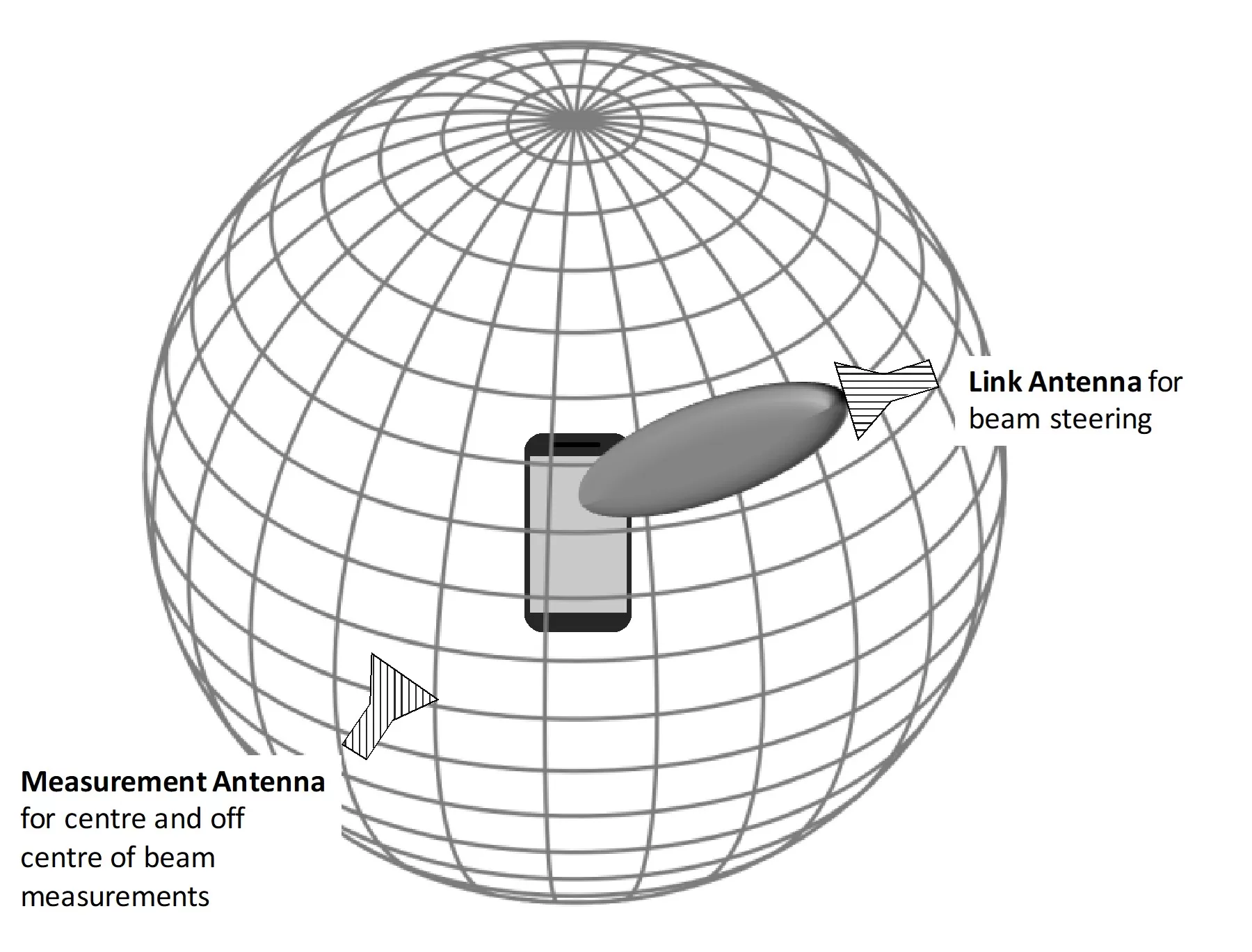
This methodology allows for testing with a full degree of freedom for each Angle of Arrival (AoA) in the measurement setup. The goal is to comprehensively evaluate the UE’s performance under varying signal arrival angles, which is essential for multi-Rx chain devices. The full rotational freedom ensures that the UE’s ability to receive signals from different directions is thoroughly tested, simulating real-world scenarios where signals may arrive from multiple sources at different angles.
Measurement Setup with Full Degrees of Freedom for AoA1 with Fixed Angular Offset(s) Between AoA1 and AoA2
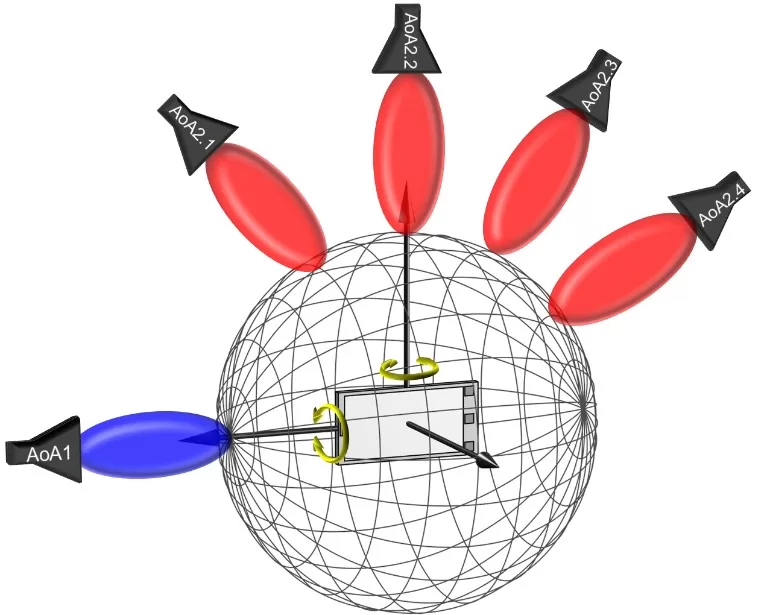
This setup focuses on scenarios where AoA1 has full degrees of freedom, but with fixed angular offsets between AoA1 and AoA2. This methodology is particularly useful for assessing the performance of UEs in environments where two dominant signal paths exist, and the angular relationship between them remains consistent. The fixed offset allows for controlled testing conditions, providing insight into how well the UE can handle consistent multipath scenarios.
Measurement Setup with Full Degrees of Freedom for AoA1 with Variable Angular Offset(s) between AoA1 and AoA2
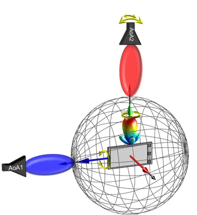
This approach introduces variability in the angular offset between AoA1 and AoA2, adding another layer of complexity to the testing environment. By varying the angular offset, this methodology simulates more dynamic environments, such as urban areas where signal paths may change due to movement or reflections. This setup is critical for understanding how UEs manage dynamically changing RF conditions.
Measurement Setup with Full Degrees of Freedom for AoA1 with Partial Freedom of Variable Angular Offset(s) between AoA1 and AoA2
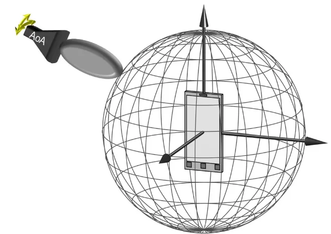
In this methodology, AoA1 retains full degrees of freedom, while the angular offset between AoA1 and AoA2 is partially variable. This setup strikes a balance between fixed and variable offsets, providing a testing scenario that is both controlled and realistic. It is particularly relevant for environments where certain signal paths may be more stable while others fluctuate.
Results and Impact
The enhanced OTA testing methodologies led to significant improvements in the device’s beamforming capabilities and handover performance. Post-deployment testing in real urban environments showed a 30% improvement in signal stability and a 25% reduction in dropped connections during handovers, compared to devices tested using previous methodologies.
Conclusion
The advancements in OTA testing methodologies introduced in 3GPP Release 18 significantly enhance the performance and reliability of NR IoT devices operating in FR2, particularly in challenging environments like urban microcellular settings. By focusing on critical areas such as advanced beamforming and mobility testing, these enhancements address the unique challenges posed by the millimeter-wave spectrum, including high path loss, susceptibility to blockages, and the necessity for precise beamforming. The improved testing protocols ensure that IoT devices can maintain robust connectivity, even in complex scenarios characterized by dense urban infrastructure and dynamic signal propagation. Practical case studies have demonstrated that these enhanced methodologies lead to marked improvements in device performance, such as a 30% increase in signal stability and a 25% reduction in dropped connections during handovers.
References
- 3GPP TR 38.871, “Study on NR Frequency Range 2 (FR2) Over-the-Air (OTA) Testing Enhancements”, Release 18, 2024.
- Qualcomm Technologies, Inc. “5G NR mmWave: Breakthrough Performance for a Wide Range of Deployments.” White Paper. 2024.
- Keysight Technologies. “Over-the-Air (OTA) Testing of 5G NR Devices.” Technical Overview.
- ETSI TR 138 874 V14.2.0, “Study on channel model for frequency spectrum above 6 GHz.”, 2017.
- IEEE. “Challenges and Solutions for OTA Testing in 5G mmWave Communications.” IEEE, 2020.