5G NR protocol stack has been designed to support lower delay and higher data rates and with Quality of service. For this purpose and in 5G NR, a new sublayer is introduced called SDAP. We will describe the functionality and operation of this sublayer.
A new SDAP sub-layer is added above the PDCP sublayer in 5GNR. PDCP is the first sublayer in the 3GPP protocol stack that receives/transmits network layer traffic (TCP/IP traffic).
Data Radio Bearer (DRB) is the logical connection used inside the 5G protocol stack to carry data PDUs. SDAP functionality is to map QoS flow to and from DRB at the PDCP sublayer in both downlink and uplink direction. Figure 1 shows the SDAP architecture.
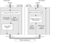
Figure 1: SDAP Architecture.
The main services and functions of SDAP include the following:
- Mapping between a QoS flow and a data radio bearer;
- Marking QoS flow ID (QFI) in both DL and UL PDUs.The following figures shows the SDAP PDU format for both DL and UL. SDAP header has the following fields:
- When SDAP receives a PDU from upper layer flow (TCP/IP), the PDU is associated with QoS for this flow. SDAP maps the flow to one of the uplink DRB. Similarly, when a downlink PDU is received at the PDCP and it contains SDAP header which is removed, and the PDU is passed to upper layer.
QFI QoS Flow ID
RDI Reflective QoS flow to DRB mapping Indication
RQI Reflective QoS Indication
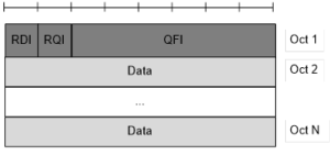
Figure 2: DL SDAP Data PDU
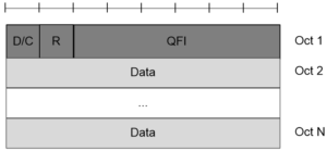
Figure 3: UL SDAP Data PDU
The following figure shows the SDAP sublayer PDU transmitted or received through the 5G protocol stack.
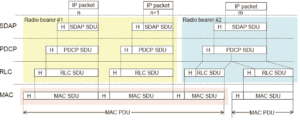
Figure 4: 5G Protocol Stack including SDAP Data PDU
To explain why SDAP is added, let us describe the QoS architecture in in LTE and 5G core network. In core network, “EPS (Evolved Packet System) bearer” is logical connection between eNB and P-GW, and P-GW connects the CN (core network) to the internet through external bearer.
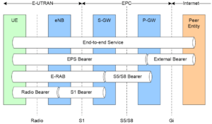
Figure 5: QoS Architecture End-to-End.
In eNB/gNB, eGTP (Evolved GPRS Tunneling Protocol) handles IP packets are handed over to PDCP in case of LTE and SDAP in case of 5G NR. The eGTP carries the IP packets between CN and RAN, this is called “EPS Bearer”.
In LTE, QoS is performed per EPS bearer, so EPS bearers and data radio bearers have a one to one mapping. The QoS is managed based on EPS bearer in both the EPC and RAN. All types of traffic mapped to the same EPS bearer receive the same level packet treatment (packet delay, packet drop). In LTE if multiple applications are running in a mobile terminal, in the eNB for each, there is a EPS Bearer, it has an associated QoS Class Identifier (QCI) and an Allocation and Retention Priority (ARP), and then each QCI, namely EPS Bearer is characterized by priority, packet delay and acceptable packet loss rate.
But in 5G CN QoS is performed on the basis of IP flow instead of EPS bearers to achieve more flexible and finer QoS control thus the addition of SDAP sublayer. This enables multiple IP flows flowing through a single EPS bearer between the CN and gNB to be individually subjected to radio bearer mapping. The bearer concept is not considered in the 5G CN while 5G NG-RAN will maintain the radio bearer concept.
Mapping between a QoS flow and a data radio bearer:
The “QoS Flow” is the finest granularity of QoS differentiation in the PDU Session. A QoS flow can either guarantee the bit rate or not. A QoS Flow ID (QFI) is used to identify a QoS Flow in the 5G System. User Plane traffic with the same QFI within a PDU Session receives the same traffic treatment (e.g. packet delay, loss, scheduling, admission). The QFI is carried in an encapsulation header on N3 (and N9) i.e. without any changes to the e2e packet header. QFI shall be used for all PDU Session Types. The QFI shall be unique within a PDU Session. The QFI may be dynamically assigned or may be equal to the 5QI (5G QoS Identifier).
Marking QoS flow ID (QFI) in both DL and UL PDU:
Reflective mapping:
Reflective QoS means that the UE maps UL User Plane traffic to QoS Flows (without SMF provided QoS rules). This is achieved by creating UE derived QoS rules in the UE based on the received DL traffic. It is possible to apply Reflective QoS and non-Reflective QoS concurrently within the same PDU Session.
When the UE supports Reflective QoS functionality, the UE shall create a UE derived QoS rule for the uplink traffic based on the received DL traffic if Reflective QoS function is used by the 5GC for some traffic flows. The UE shall use the UE derived QoS rules to determine mapping of UL traffic to QoS Flows. For each DRB, the UE monitors the QFI of the DL packets and applies the mapping in the UL. To enable reflective mapping, the NG-RAN marks DL packets with QFI.
Explicit mapping:
The NG-RAN may configure the mapping by RRC, an UL QoS Flow to DRB mapping.
This is really good information. I will continue in another sequel article