


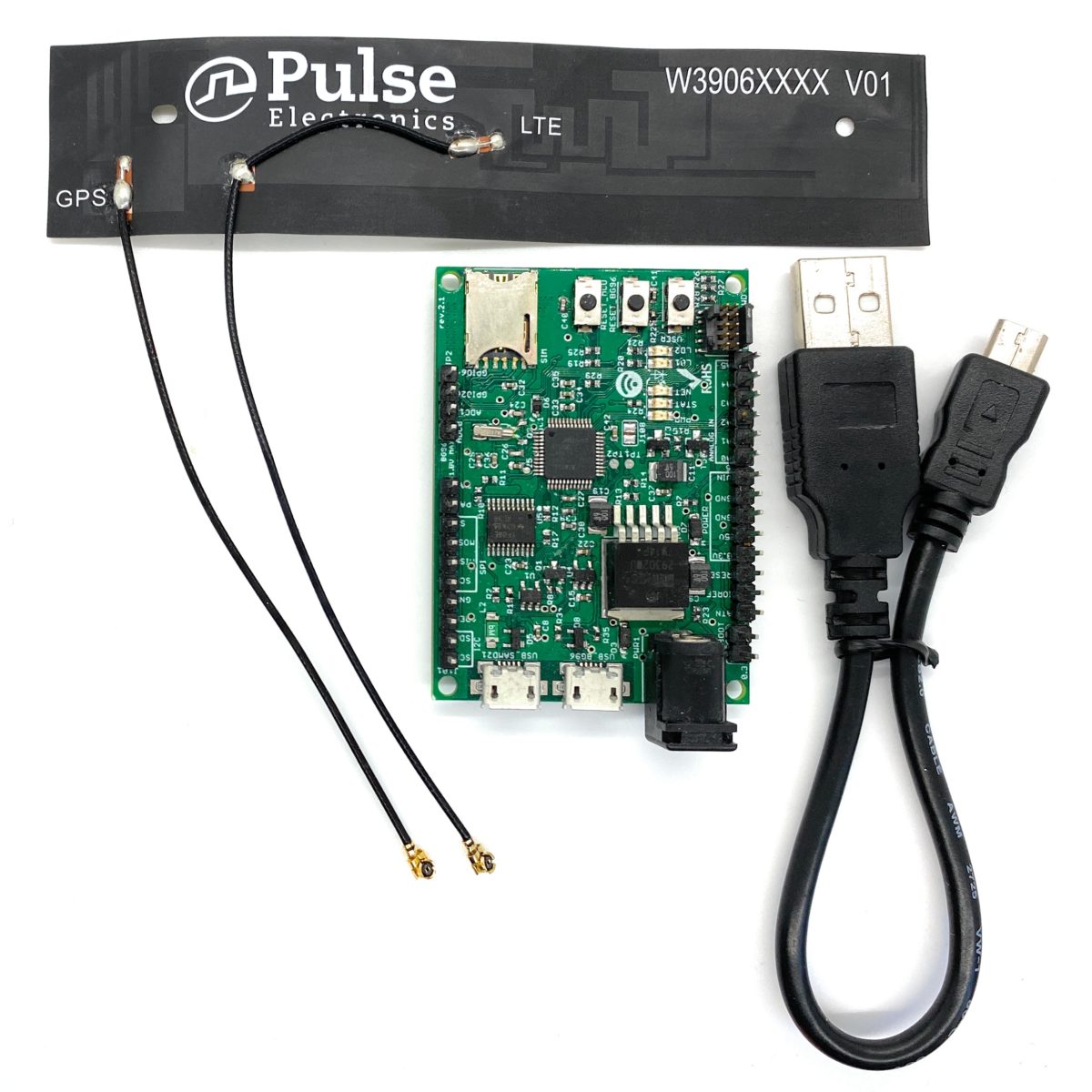
Description
The NB-IoT kit is a cellular and GPS kit that can be used for the 5G wireless technology. The kit includes a hardware board, LTE&GPS antenna, and a USB cable. The board is a powerful board that features a microcontroller and wireless modem. The microcontroller is an Atmel’s SAMD21G18A MCU which features a 32-bit ARM Cortex® M0+ core. The wireless modem is BG96 which is an embedded IoT (LTE Cat-M1, LTE Cat-NB1 and EGPRS) wireless communication module. BG96 wireless modem provides a maximum data rate of 375Kbps downlink and 375Kbps uplink. It features ultra-low power consumption, provides data connectivity on LTE-TDD/LTE-FDD/GPRS/EDGE networks, and supports half-duplex operation in LTE networks. It also provides GNSS to meet customers’ specific application demands
The board provides rich sets of Internet protocols, industry-standard interfaces (USB/UART/I2C/Status Indicator) and abundant functionalities. The board offer a high integration level and enables integrators and developers to easily design their applications and take advantage of the board low power consumption, many functionalities, and USB drivers for Windows 7/8/8.1/10, Linux and Android.
The kit board is a rich hardware board that can be used for the latest 5G wireless technology and enables a variety of smart and 5G applications for devices, and acts as a great educational tool for learning about 5G and 32-bit application development. It enables large number of applications such as wireless POS, smart metering, tracking, smart transportation, smart buildings, smart city, and smart homes.
The board is also compatible with Arduino and Arduino software (IDE). Arduino sketches and examples are provided with the kit and additional sketches can be developed and uploaded to the board.
- Atmel ATSAMD21G18 MCU
- Quectel BG96 NB-IoT module
- External GPS antenna Connector
- External LTE antenna connector
- Supports LTE NB-IoT and Machine Type Communications (MTC)
- Supports EGPRS
- Global Frequency Band B1/B2/B3/B4/B5/B8/B12/B13/B18/B19/B20/B26/B28/B39 (B39 for Cat.M1 only) for LTE and 850/900/1800/1900MHz for EGPRS
- Supports the protocols TCP/UDP/PPP/ SSL/ TLS/ FTP(S)/ HTTP(S)/ NITZ/ PING/ MQTT
- Supports SMS
- Supports GNSS technology (GPS, GLONASS, BeiDou/Compass, Galileo, QZSS)
- Compact board size of 58mm x 42mm
- Nano USIM card slot
- Arduino IDE Compatible
- Works with Windows, Linux, or Android
- Ready for smart applications and development (smart home, smart city, smart transportation, smart metering, smart farming, smart waste management, asset tracking, location, navigation, mapping, and timing applications). Application such as Gas Detector, Soil PH Tester, Optical Sensor, Machinery Alarm System, Irrigation Controller, Elevator, Asset Tracking Electronics, Person/Pet Tracking, Water/Gas Metering, Smart Parking System, Fire Hydrant, Smoke Alarm, Trash Bin, Street Lighting
- The board can operate on an external power supply of 3.3V to 5V. The recommended voltage is 5V.
- The board can be powered via the USB connector or with an external DC power supply. The power source is selected automatically.
- External DC Power supply (non-USB) can be provided from an AC-to-DC adapter (such as a wall-wart) or battery, and can be connected using a 2.1mm center-positive plug connected to the board’s power jack, or directly to the GND and VIN pins.
- Each of the 14 general purpose I/O pins on the board can be used for digital input or digital output using pinMode(), digitalWrite(), and digitalRead() Pins used for PWM can be using analogWrite()function. All pins operate at 3.3 volts. Each pin can source or sink a maximum of 10 mA and has an internal pull-up resistor (disconnected by default) of 20-60 K ohm.
The width and length of the board is 48mm (width) by 52 mm (length). The board have four screw holes in each corner that allows the board to be attached to a surface or case.

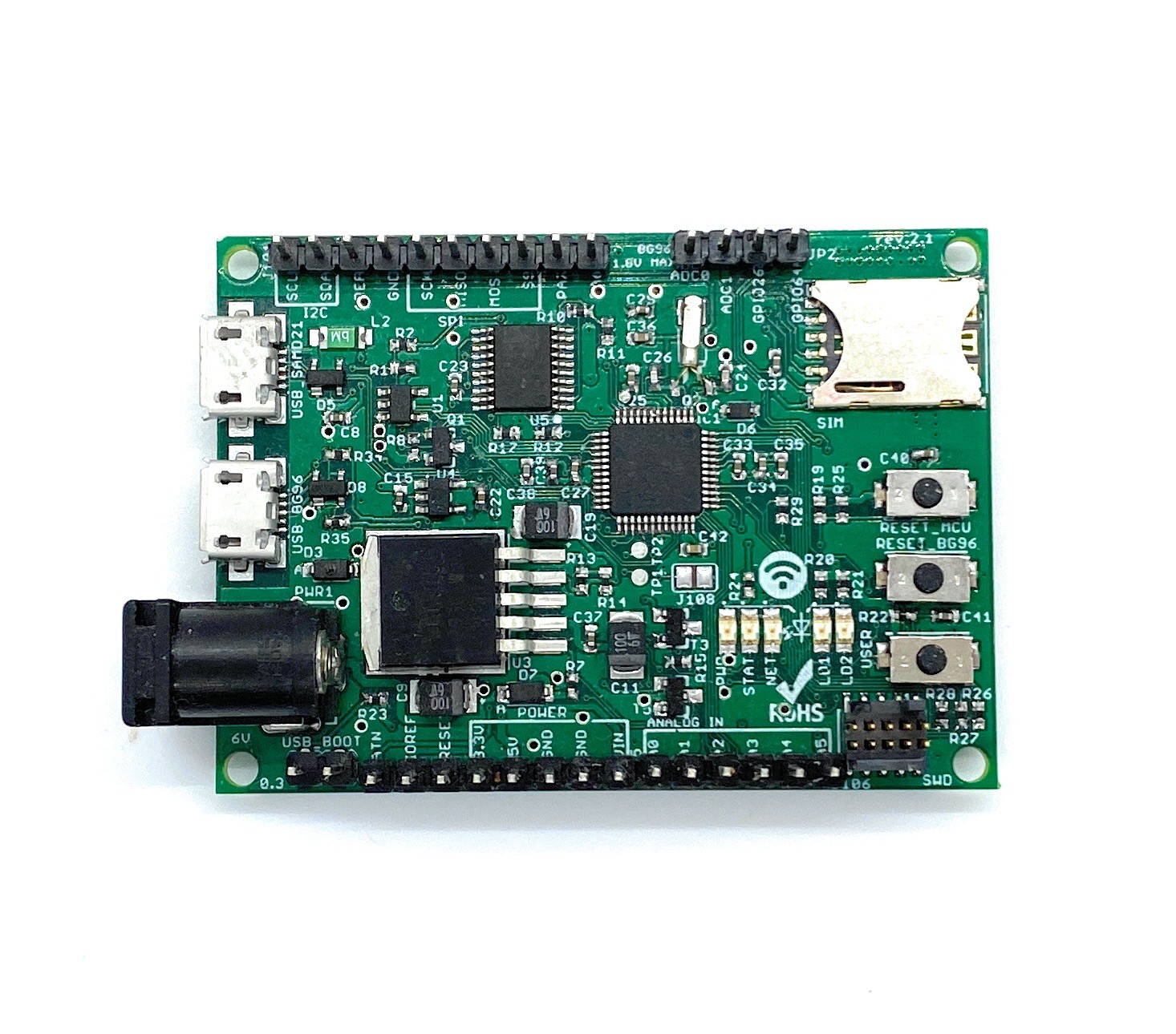
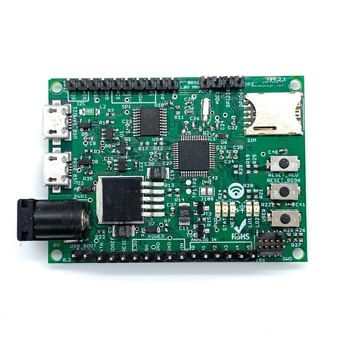
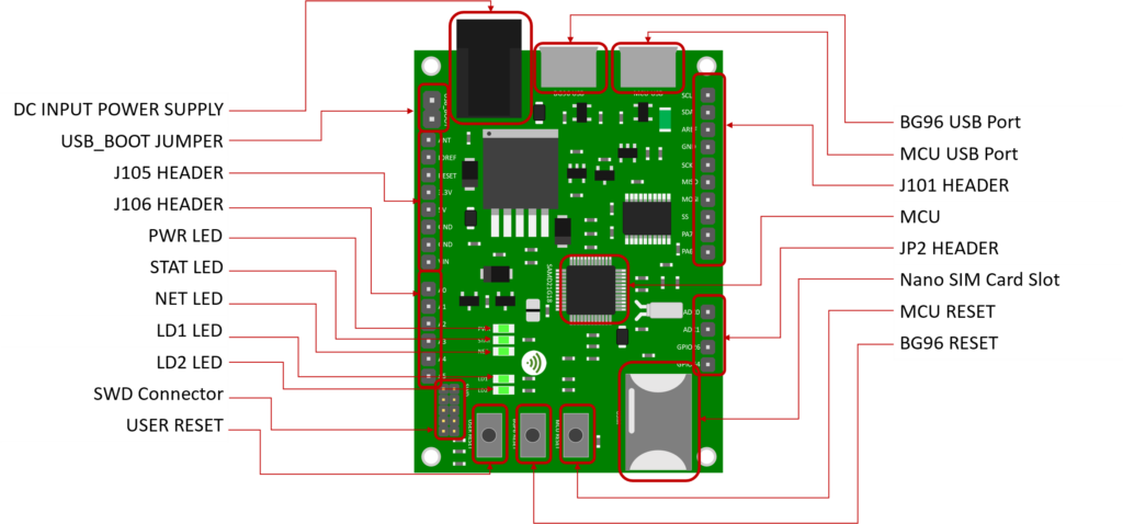 Board Top Side – Key Components
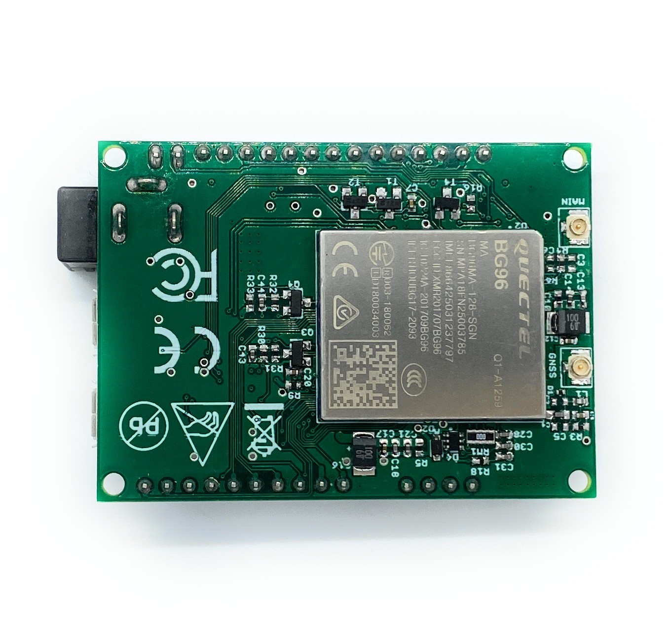
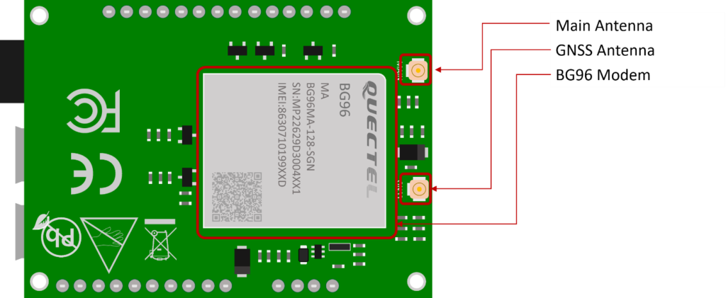 Board Bottom Side – Key Components
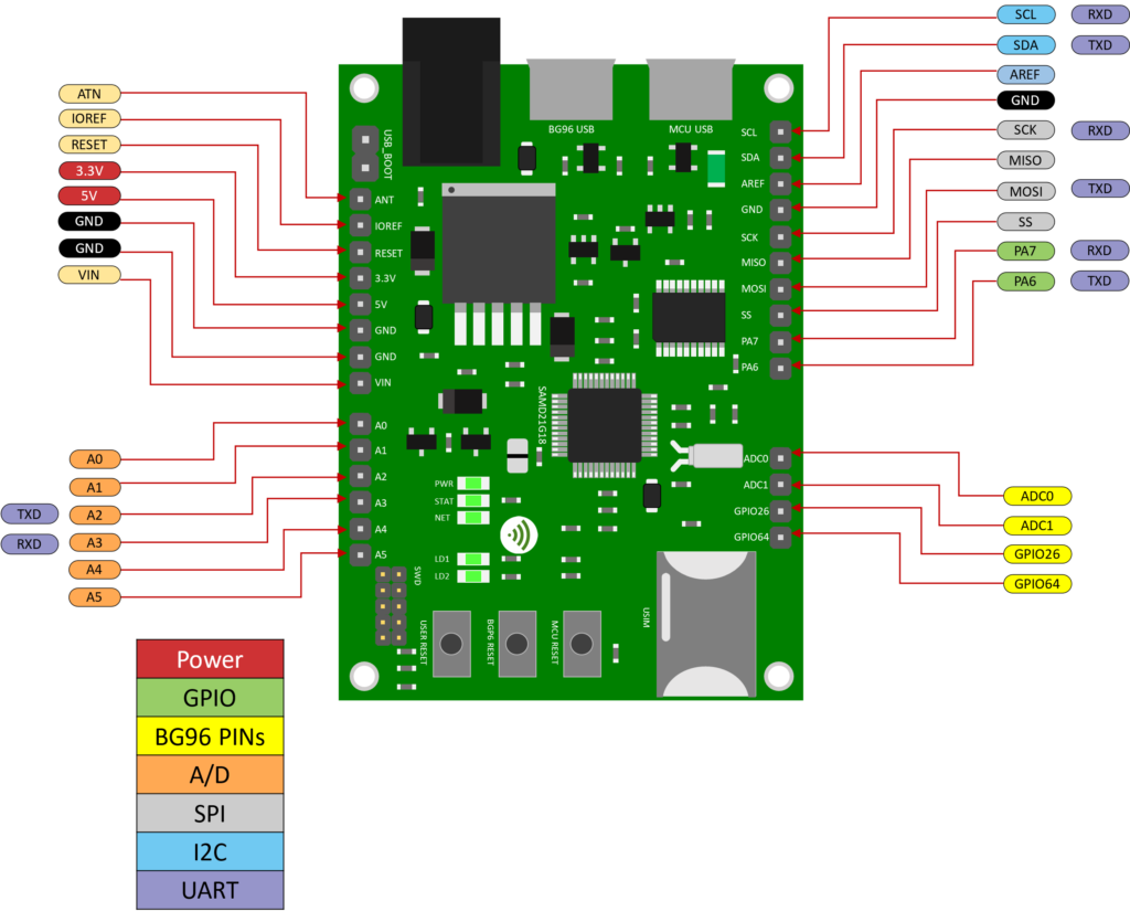
Pinout of the Board
| Technical Specification | |
| Microcontroller (MCU) | Atmel ATSAMD21G18, 32-Bit ARM Cortex M0+ |
| Clock Speed | 48 MHz |
| Flash Memory | 256 KB |
| SRAM | 32 KB |
| NB-IoT Module | Quectel BG96 |
| Dimension | 48mm (width) by 52 mm (length) |
| Weight | 18 grams |
| Power Supply | DC Power Supply (3.3-5V), USB (5V), VIN (3.3-5V), or Battery |
| LED | LED1, LED2, Power LED, Status LED, Netlight LED |
| Interfacing Logic Voltage Level (Operating Voltage) | 3.3V |
| Voltage output | 5V, 3.3V |
| RESET buttons | Two; one for MCU and one for BG96 |
| User-defined Button | 1 connected to MCU |
| General-purpose digital I/O Pins | 14 (A0-A5, PA6, PA7, SS, MOSI, MISO, SCK, SDA, SCL) |
| GPIO | 2 connected to BG96 |
| ADC | 2 connected to BG96 |
| USB | 2 |
| I2C | 1 |
| SPI | 1 |
| UART | 1 |
| ADC pins | 6 (8/10/12-bit ADC channels) |
| DAC pin | 1 (10-bit DAC) |
| External interrupts | 14 (All general-purpose PINs) |
| PWM pin | 6 |
| DC Current per I/O Pin | 10 mA |
| JTAG Debug | Cortex Debug Connector (Single Wire Debug) |
| USIM | Nano |
| GNSS | GPS, GLONASS, BeiDou/Compass, Galileo, QZSS |
| Antenna | 1 main antenna and 1 GPS antenna |
| Band | LTE-FDD, B1/B2/B3/B4/B5/B8/B12/
B13/B18/B19/B20/B26/B28 LTE-TDD: B39 (for Cat M1 only) |
| Certification | FCC, CE |
| Mobile Operator Certification | Verizon and currently for AT&T |
Notes:
- UART can be programmed through any of general-purpose pins.
- SPI can be programmed through any of general-purpose pins.
| PIN | DIRECTION | Description |
|---|---|---|
| DC Power Jack | I | The board can be supplied with power either from the DC power jack (3.3V-5V), the USB connector (5V), or the VIN pin of the board (3.3V-5V) |
| LED (PWR) | O | LED is lighted on when the board is power on from the MCU USB port |
| LED1 (USER) | O | LED which can be controlled from MCU (D25). When the pin is HIGH value, the LED is on, when the pin is LOW, it is off |
| LED2 (USER) | O | LED which can be controlled from MCU (D26). When the pin is HIGH value, the LED is on, when the pin is LOW, it is off |
| LED (NET) | O | Indicate the BG96 operation status |
| LED (STAT) | O | Indicate the BG96 network activity status |
| MCU RESET button | I | Reset the MCU |
| BG96 RESET button | I | Reset the BG96 module |
| User Button | I | Connected to digital pin, D0, of MCU and can be used for user-defined purposes |
| IOREF | O | Provides the voltage reference with which the MCU operates. A device can read the IOREF pin voltage and select the appropriate power source or enable voltage translators on the outputs for working with the 5V or 3.3V |
| 3.3V | O | 3.3V generated by the on-board regulator. Maximum current drawn is 300 mA. The regulator also provides power to the MCU and BG96 |
| 5V | O | 5V generated from the board. The board can be supplied with power either from the DC power jack (3.3V – 5V), the USB connector (5V), or the VIN pin of the board (3.3-5V). Supplying voltage via the 5V or 3.3V pins bypasses the regulator and can damage the board if it is not sufficiently regulated (This is not recommended) |
| GND | Ground | |
| VIN | I | Input voltage to the board when it uses an external power source (as opposed to 5 volts from the USB connection or other regulated power source). You can supply voltage through this pin, or if supplying voltage via the power jack, access it through this pin |
| A0 | IO | Six analog inputs which can provide up to 12 bits of resolution (i.e. 4096 different values). By default, each input measures from ground to 3.3 volts, though is it possible to change the upper end of their range using the AREF pin
A0 can also be used as a DAC output and provides a 10 bit voltage output with analogWrite() function Analog pins can be used as GPIOs |
| A1 | IO | |
| A2 | IO | |
| A3 | IO | |
| A4 | IO | |
| A5 | IO | |
| SCL | IO | I2C. The SCL (clock line). Can be used as GPIO |
| SDA | IO | I2C. The SDA (data line). Can be used as GPIO |
| AREFA | I | Input reference voltage for the analog inputs used for either he ADC or the DAC |
| SCK | IO | SPI Interface. Can be used as GPIO |
| MISO | IO | SPI Interface. Can be used as GPIO |
| MOSI | IO | SPI Interface. Can be used as GPIO |
| SS | IO | SPI Interface. Can be used as GPIO |
| PA7 | IO | GPIO. Can be used as GPIO |
| PA6 | IO | GPIO. Can be used as GPIO |
| Cortex Debug Connector | IO | Using Single Wire Debug to burn bootloader and debug the board |
| ADC0 | I | Connected to BG96. General purpose analogue to digital converter |
| ADC1 | I | Connected to BG96. General purpose analogue to digital converter |
| GPIO26 | IO | Connected to BG96. General purpose IO |
| GPIO64 | IO | Connected to BG96. General purpose IO |
| USIM | I | Used to insert a Nano USIM. Connected to BG96 |
| USB Boot | I | Connected to BG96. Force the BG96 to enter emergency download mode |
| USB1 | IO | Connected to MCU |
| USB2 | IO | Connected to BG96 |
